All about the roof..... September, October, November 2002
|
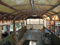
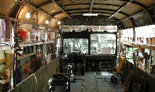
At this point
the entire roof is "CUT" in the middle of all roof uprights. The raising
"RODS" have been installed and we are ready to go up. |
|
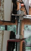
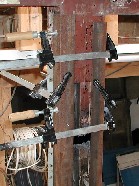
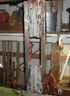
The 3/4"
threaded rods are installed to riveted first and then welded angle iron plates. The
separation in the upright shows that we have started raising the roof. |
|
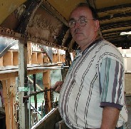
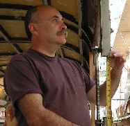
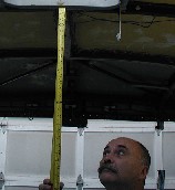
That's me in the
upper picture. I know I look a little concerned but I wasn't. The Engineer (my wife Kathy)
looked everything over and told me it was OK to start turning the screws. NOT ! By
3pm, my brother Vince had all he could do to stay awake. He's not used to this kind
of work and by 1pm he usually needs a nap. He's one of those PHD types. But with his
help and Mother too, we got the roof to go up the full 12 inches.
Notice that the crew is partying here. I had to put a stop to this. Cut back on
the full bodied Pepsi and switched them over to water.
I took about 3 hours to raise the roof 12 inches. |
|
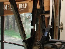
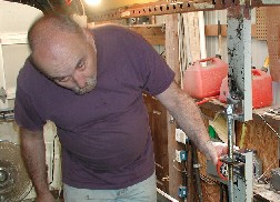
On the two
center column uprights, I had installed this makeshift sliding angle irons pieces to keep
the roof aligned at all times. The Treaded rods were placed on uprights about 8 feet from
the front and 6 feet from the rear and on each side for a total of 4 raising rods. |
|
At this point
the roof is up the full 12 inches. I measured a dozen times to make sure that the roof was
within 1/32" of where it should be or closer. My son (the machinist) was pretty
upset. I tried to explain to him that 1/32 has got to be acceptable when you
consider the bus is 35 feet long. I gave up. |
|
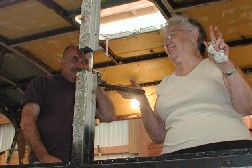
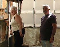
Vince kept an
eye on the tape measure. I'm excited that all went to well. |
|
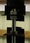
The uprights are
actually a metric measured tube steel approximately 1 3/4 inch square. There is actually
more steel holding up the roof than before. In later pictures you will see that we
installed cross bracing tubes as well. |
|
Thanks to
Mother, Brother Vince, and Kathy for all the help in raising the roof. Thanks to my son
Tony for doing the MIG welding of the tube steel uprights. Great Job!
You guys get the first ride! |
|
Final check! The
inside of the Bus is now 87 inches from original floor to the ceiling. That will give me
room for a 2 inch foam floor for insulation plus a 3/4 inch plywood rough floor. And....
in the ceiling I will have room for ducts and cabling. I expect to have an 80"
ceiling height, +/-. |
| Although there
are relatively few pictures, there was a lot of effort put into things that did not
show... like... I blocked the bus in 6 places to insure that when I cut the roof, the bus
would not flex. I had removed the entire AIRBOX over the engine and the radiators
and the Mitrebox and the associated peripherals like the water filler tank. I also
had to remove the back ceiling mounted Air conditioning coil for the rear cabin area. |
What an
unbelievable mess the Mitrebox had caused by leaking oil into the pan of the Airbox. It
was like cutting brownies out of a pan with slimy oil over them. Yuk! Fully 1 inch thick.
Then came the high pressure spray gun with ORANGE Cleaner to break up the oil.
While I had the Mitrebox out, I replaced the oils seals, checked the bearings and
reassembled everything. |
| After raising the roof, rebuilding the uprights, and stabilizing the bus
again, I proceeded to lift the airbox. Although I do not anticipate changing the
engine, I did want to insure enough space in the engine compartment for a turbo air fed
engine if the need should arise. So before I started building the inside of the bus,
I wanted this part to be complete. Here are a few pics of the completed Airbox
renovation. |
|
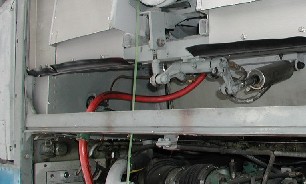 |
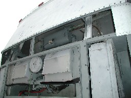
You can see that there is a 10 inch rise from the normal location of the
air box. I had to install some 1 3/4 inch tube steel and some 1 3/4 angle for the new
frame work. I then recovered the space with aluminum sheeting which came from the inside
roof panels that I had removed. |
|
As you can see, everything is re-installed including the radiators and the
water tank and now I have an additional 12 inches of rear area to cover. I will
cover this space with removable panels for each access. Of course, I will also have
to get a new and longer V-belt for the mitrebox. |
| In the latter
part of November, I installed the oil system to feed my barn furnace and a few ducts to
heat the barn during the cold Maine Winters. |
In December I
ordered 7 sheets of Aluminum. 0.065 inches thick and in 4 x 10 size. They cost me roughly
$70 per sheet delivered. |
| I ordered 5000
each 3/16" Aluminum Blind Rivets with Aluminum mandrels. I also ordered 500 each
1/4" Aluminum Blind Rivets with Aluminum mandrels. |
I searched for a
pneumatic pop rivet gun and found one at Harbor Freight. $60. I purchased it for
3/16" rivets. But I rebuilt one of the smaller nozzles that I new I would not use to
take the 3/16" mandrel for a 1/4 rivet. It works great. It probably could
not handle a Steel mandrel of the same size. But who cares. No STEEL Rivets
here. |
|
|
| Coming SOON! |
|
| Siding
installation through January and February 2003 |
Come back soon,
Ya'll hear? See Ya! |